The FunTechHouse project, a open source home automation system - KCC-734EA New humidity sensor
Abstract
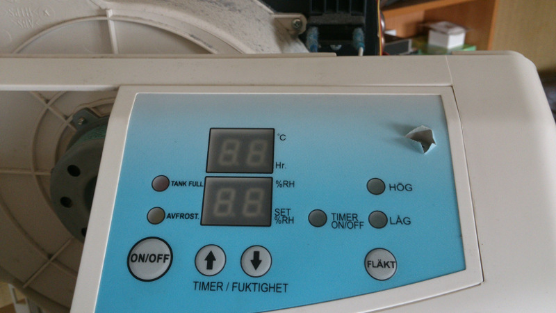
One day my dehumidifier stopped working as it should and most of the time the display just showed a strange F1, instead of the relative humidity value. So I contacted the maker and they told me F1 means sensor error (and that this was the end of the line for this device).
So my intention was to dissect and have a look inside and maybe have some fun with it, but ended up with this little repair.
The code
The code for this project can be found over at github. Since it is based on the FunTechHouse_RoomTemperature project it is in that git but on a branch called KCC_735EA__AM2302.
The repair
About
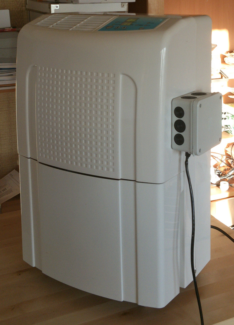
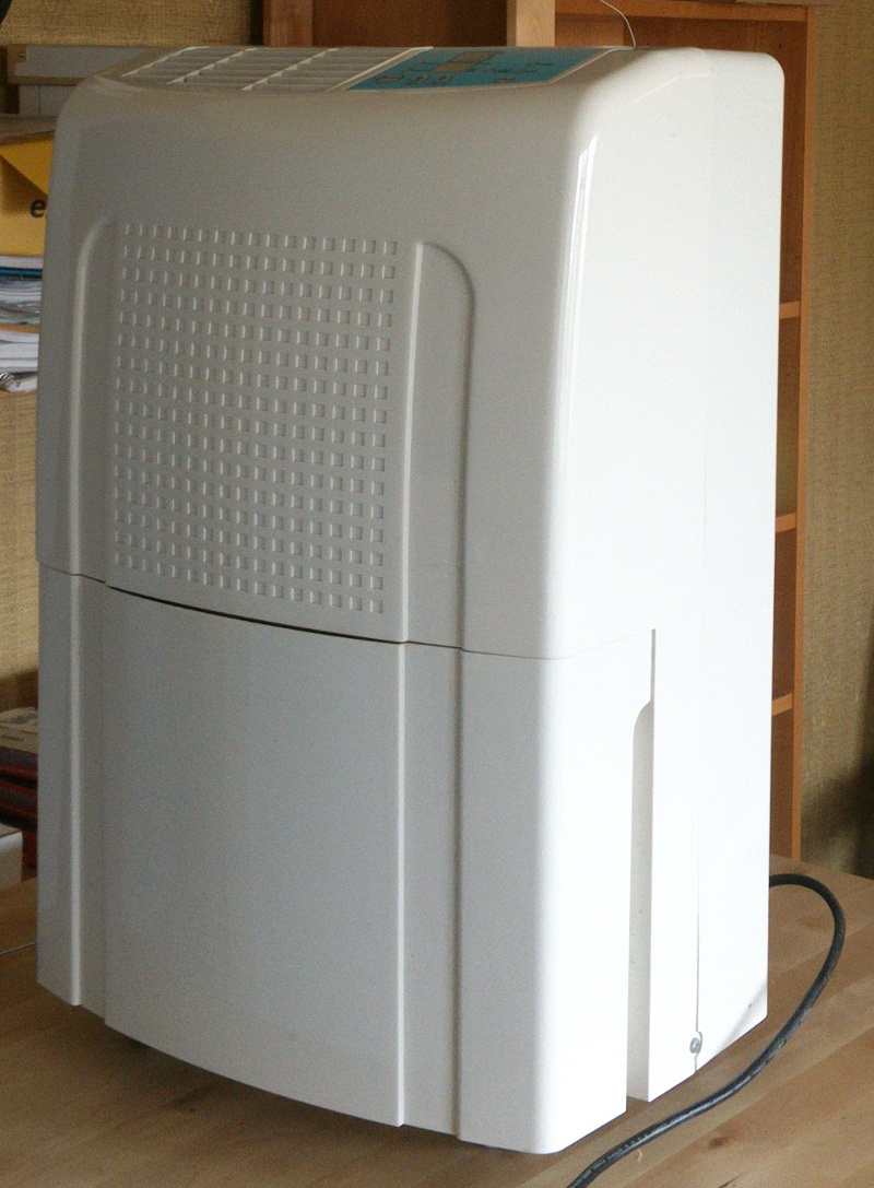
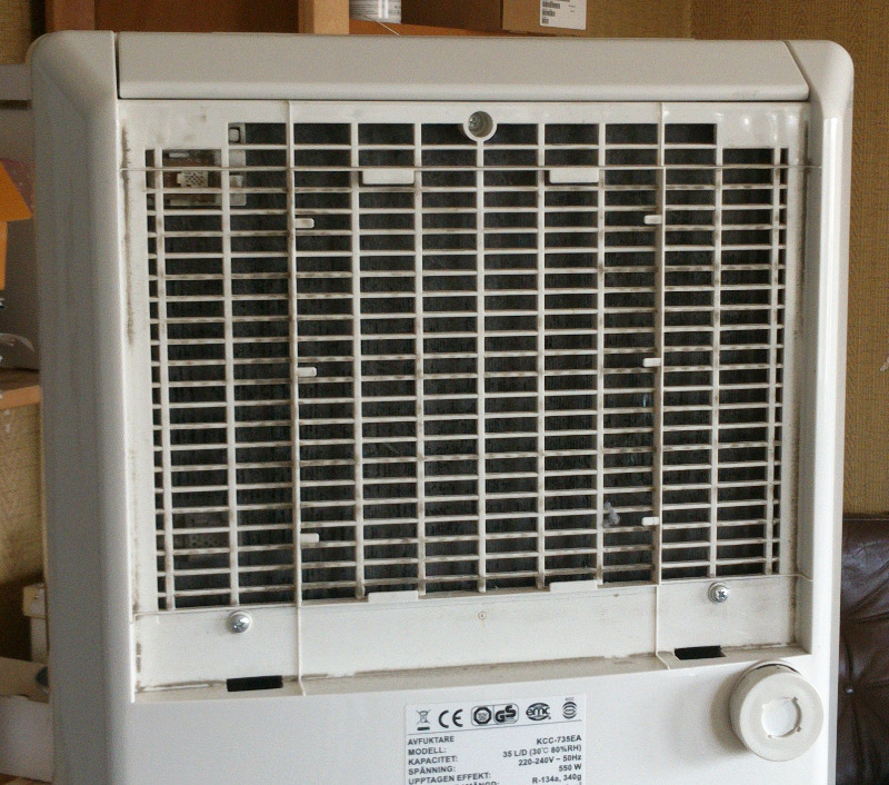
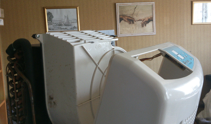
This dehumidifier looks quite boring with the classic design.
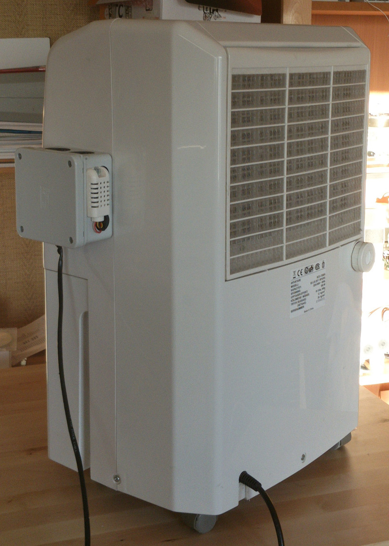
A nice feature is the possibility to connect a hose on the back so you don't have to empty the container all the time. (That's the knob on the right).
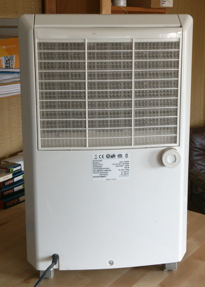
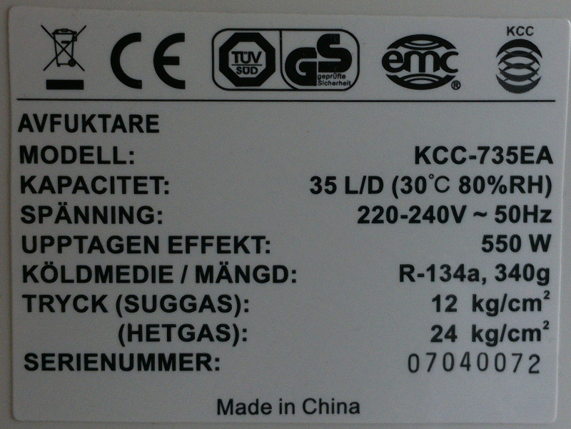
On the back is a sticker with the data on this device.
Locate screws
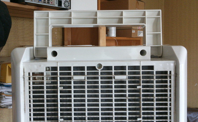
On the back I found some screws under the dust filter.
And then there is some more under the handle.
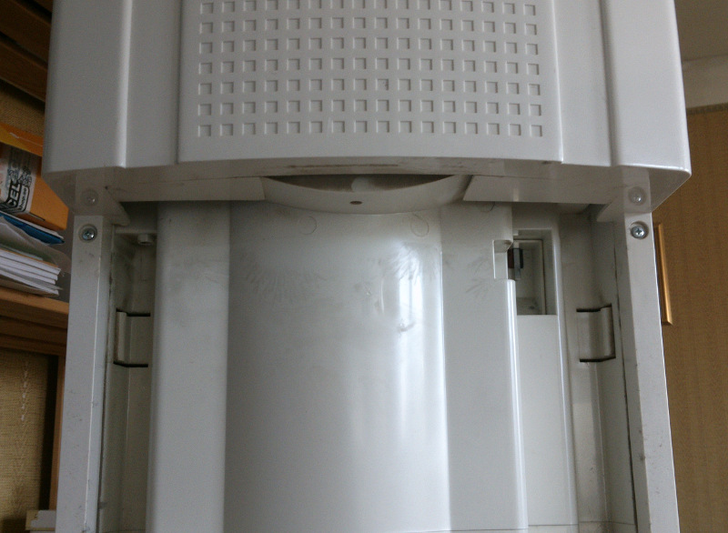
Then on the front there was a couple of screws behind the drip tray. And after I removed all of those screws the back cover fell right off.
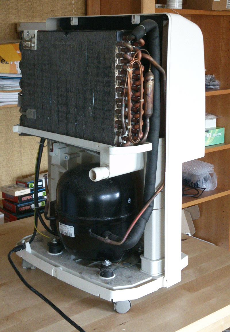
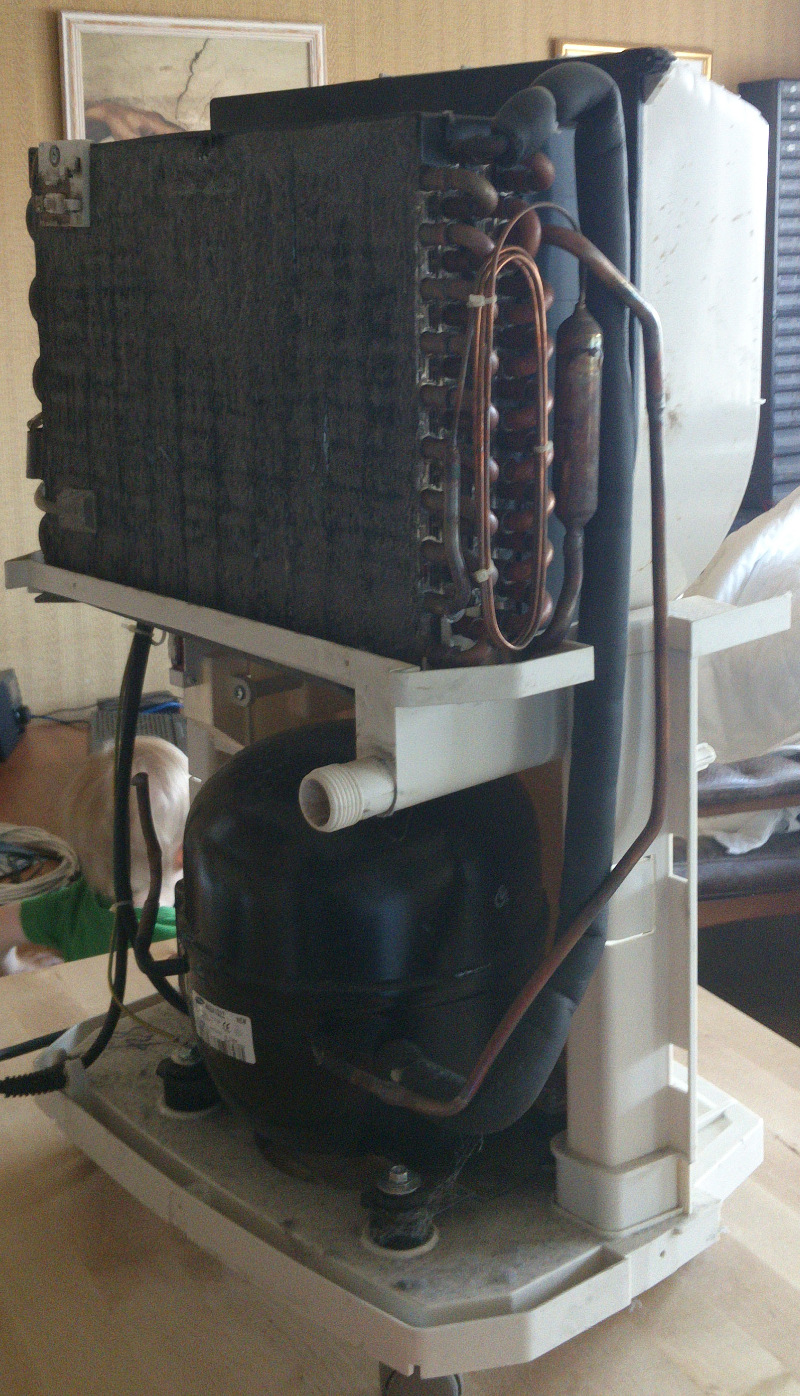
Now the compressor and condenser was visible, and you can see that how much it looks like a inner workings of the fridge in the kitchen.
Also that there is a lot of dust and dirt on the condenser!
When removing the front I needed to be a little more careful since there is some cables going to and from the control panel.
At this point I noticed that I could not remove the panel since there was a hidden screw under the plastic cover. So I simply cut a hole in the plastic to get access.
Troubleshooting
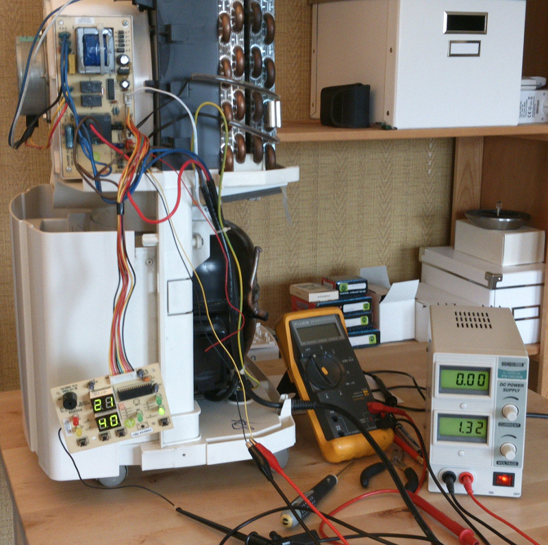
At this point I had access to all the stuff I needed to start the troubleshooting.
Here you can clearly see the main power board that controls the compressor and the fan, and communicates with the control panel hanging down in its cable.
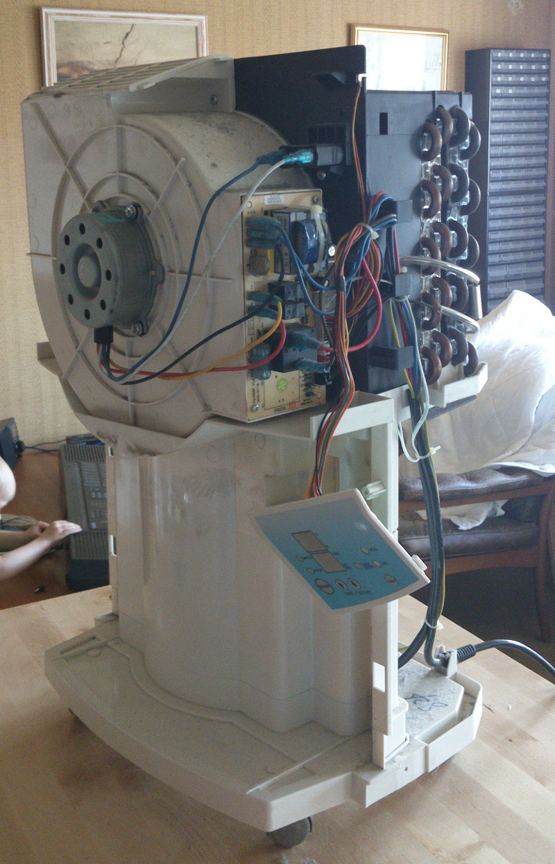
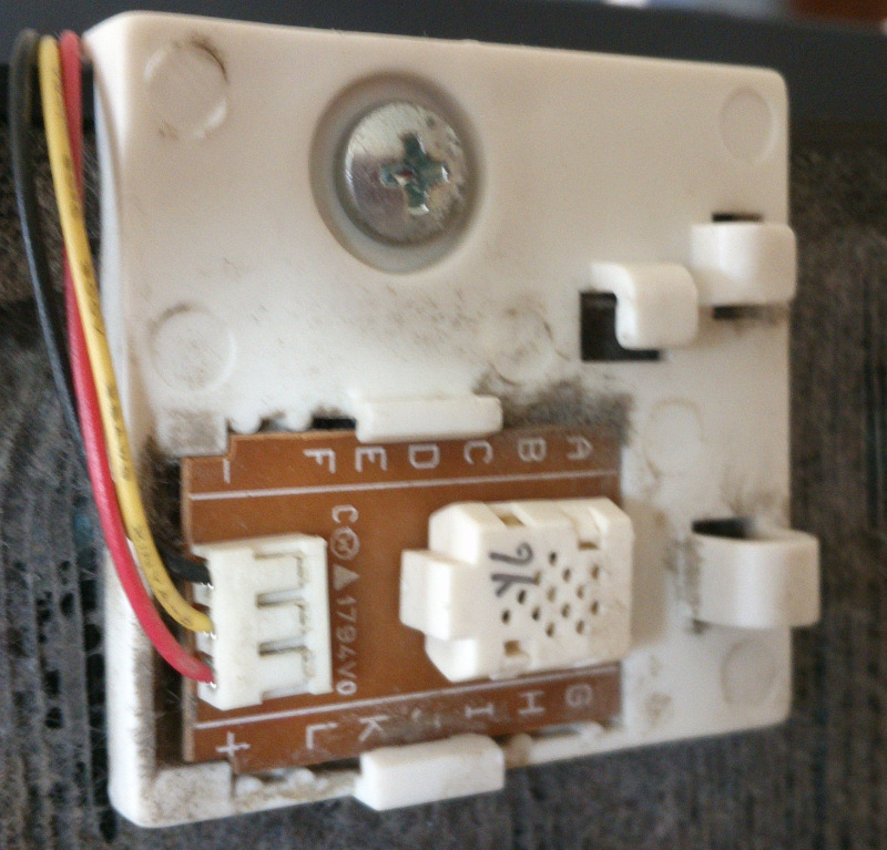
On the backside up on the left you can see the humidity sensor.
This sensor board is connected with 3 cables, a red, a yellow and a black cable.
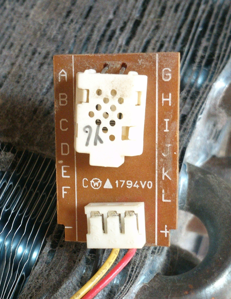
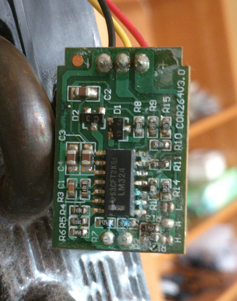
The only thing I know about this card at this point in time is that the backside tells another story. There is oxidation all over the card, and I could not figure out why there was a issue with it...
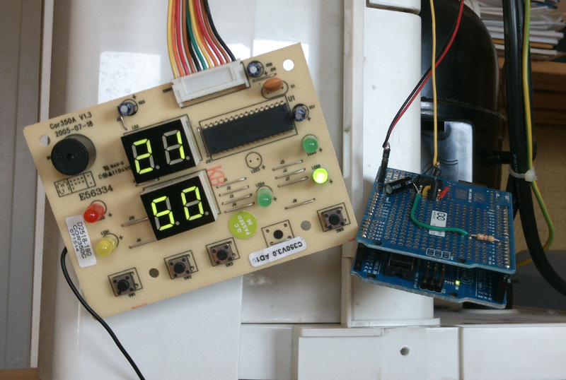
However I noticed that there sometimes was a low voltage dc signal between the yellow cable and the black cable, and at those moments the control panel showed a value and not F0!
I also noticed that there always was a 5V between the red and black cable, and that the black was connected to what look like ground the main board.
So I took a wild guess and connected a bench power supply and noticed that when I increased the voltage the display stared to show values again. And wither higher voltage, I got a higher value in the relative humidity display. I also noticed that if there was 0V in I got the F0 error code!
More or less I could simulate the broken sensor with my power box :)
Simulate the sensor
Therefor I created a spreadsheet and stated to enter the different voltages and displayed humidity. The 2 columns on the left is the input voltage and the resulting reading on the display.
| Volt | Reading | XV/5V/255 | approx | RH%*1.63 | error steps | error Volt |
|---|---|---|---|---|---|---|
| 0 | F1 | |||||
| 0.9 | LOW | |||||
| 1.0 | 30 | 51 | 1.70 | 49 | 2.10 | 0.041 |
| 1.1 | 35 | 56 | 1.60 | 57 | -0.95 | -0.019 |
| 1.3 | 40 | 66 | 1.66 | 65 | 1.10 | 0.022 |
| 1.4 | 45 | 71 | 1.59 | 73 | -1.95 | -0.038 |
| 1.6 | 50 | 82 | 1.63 | 82 | 0.10 | 0.002 |
| 1.7 | 55 | 87 | 1.58 | 90 | -2.95 | -0.058 |
| 1.8 | 55 | 92 | 1.67 | 90 | 2.15 | 0.042 |
| 1.9 | 60 | 97 | 1.62 | 98 | -0.90 | -0.018 |
| 2.0 | 60 | 102 | 1.70 | 98 | 4.20 | 0.082 |
| 2.1 | 65 | 107 | 1.65 | 106 | 1.15 | 0.023 |
| 2.2 | 70 | 112 | 1.60 | 114 | -1.90 | -0.037 |
| 2.4 | 75 | 122 | 1.63 | 122 | 0.15 | 0.003 |
| 2.5 | 80 | 128 | 1.59 | 130 | -2.90 | -0.057 |
| 2.7 | 85 | 138 | 1.62 | 139 | -0.85 | -0.017 |
| 2.8 | HIGH | |||||
| 1.63 |
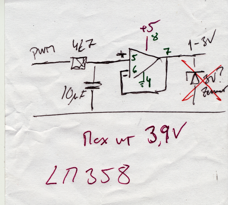
So I created something that could send this value, a PWM signal though a RC filter and a OP amp (to secure the output). Since I needed a voltage that I could change between 1V and 3V, I noticed that there was no need to power the OP-amp with more than 5V, since that would give me max 3.9V out. Also I used a Arduino to send the PWM signal.
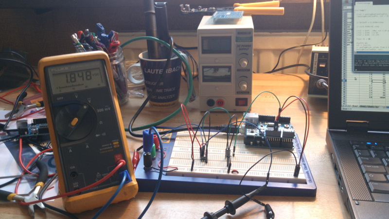
A quick test on a breadboard showed that the design seemed to work as intended.
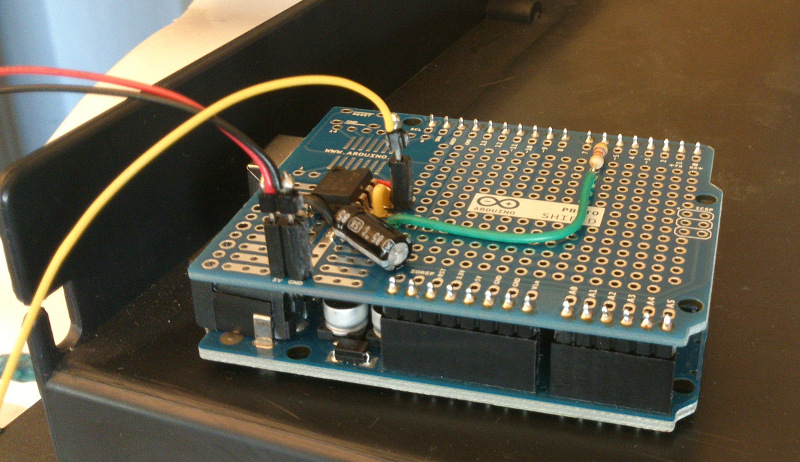
The shield and AM2302
It was time to finalise the repair so I created a shield, and connected it to the same cables the old sensor used in the dehumidifier.
And did some test runs that verified that if I sent the voltage levels like the one for 50% relative humidity, then value 50 actually showed on the display.
It worked quite well for all values from LOW to HIGH.
Then I connected the AM2302 temperature-humidity sensor, with sensor code from Lady Ada and it worked right out of the box.
More info on the AM2302 / DHT22 sensor can be found over at the Lady Ada page http://www.adafruit.com/products/393, and have a look at the https://github.com/adafruit/DHT-sensor-library.
So I read the AM2302, converted the value and sent it to the device. And it just works!
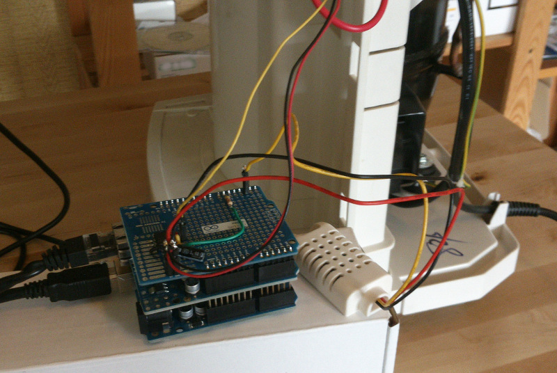
As a little bonus I added the Ethernet shield and some MQTT code to send the value and alarms to a MQTT server (more on this later).
Since I could not fit the big Arduino in the existing box, I attached a junktionbox on the outside and put it all in there.
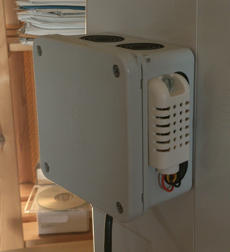
The result
The end result looks like this.